RC2014: Z80 Assembly for Catgirls 😻
“RC2014 is a simple 8 bit Z80 based modular computer originally built to run Microsoft BASIC. It is inspired by the home built computers of the late 70s and computer revolution of the early 80s. It is not a clone of anything specific, but there are suggestions of the ZX81, UK101, S100, Superboard II and Apple I in here. It nominally has 8K ROM, 32K RAM, runs at 7.3728MHz and communicates over serial at 115,200 baud.” - RC2014 Homepage
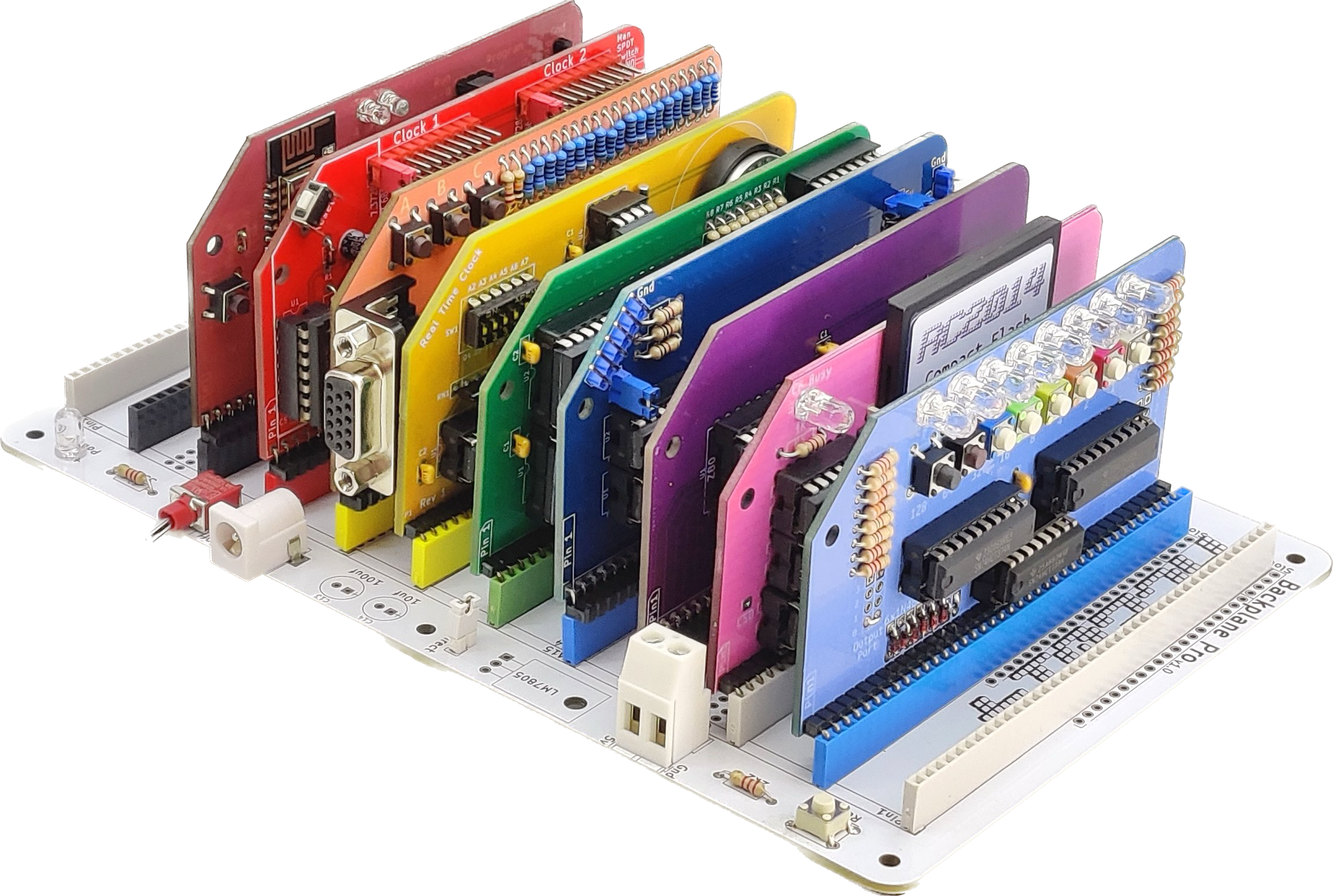
I soldered this kit together recently, which was an undertaking that I underestimated. The Pro kit (pictured above) requires over 1,000 joints to be soldered just on the backplane itself.
My kit came with the compact flash and digital I/O modules. With the ROM jumpers set to the correct page, the kit boots to the Z80 SBC Boot ROM, which can then boot the install of CP/M 2.2 that comes preinstalled on the CF card.
Editor Woes
I might one day learn how ED.COM works. Today is not that day. Instead, I’ve installed NVEDIT
using DOWNLOAD.COM. There’s a copy of DOWNLOAD.COM preinstalled on the virtual A: drive.
Workflow will differ depending on your editor of choice, but writing assembly will be the same as
long as you’re using the standard CP/M tools for development. I may write a future post looking into
Small Computer Monitor, at which point
your assembly mnemonics and syntax will vary slightly.
A Quick Aside
CP/M ships with three executables, ASM.COM, DDT.COM, and LOAD.COM. Once you’ve written your
source code, you can assemble your program to hex with ASM FILE.ASM. The file extension is also
implicit if you’ve named your file .ASM. This outputs a .HEX file.
You can invoke the DDT debugger on it, and execute it. If you want to build a self-contained
executable, invoke LOAD on your .HEX file and it will generate a .COM file.
There Are Eight Lights!

The Digital I/O module makes for a great first device to fiddle with. It is addressed as device 0, accepts an 8-bit value that it displays in two’s complement with 8 LEDs, and has eight momentary pushbuttons that are read back as an 8-bit value. The LEDs it comes with are very bright, though! Let’s fix that and turn them off.
The official page for this module mentions this little blurb about controlling it:
In BASIC the port can be read with the INP(0) command which will return a number from 0 to 255, and written to with OUT 0,x where x is the number to output from 0 to 255
In assembly language, the mnemonics
in a,(0)and out(0),ado the same function
Some research and trial/error led me to this simple program that will turn those lights off. On the
Apple II, a popular memory location for the ORG statement (where this program is loaded into memory)
is $8000, but in CP/M $0100 is a standard choice. Note that the h in 0100h stands for
hexadecimal, and is just the convention that CP/M’s assembler uses.
org 0100h
mvi a,00h
out (0)
ret
So, what does the rest of this do? Well, if we want none of the lights lit up, we’d want to send 0
to the device. CP/M’s assembler just uses the A register for OUT commands. So we need to stick 0
into the A register.
We’ll do this with MVI, which is the move immediate data instruction. 00h
is a hexadecimal constant for 0, and once it’s in the proper register, we just call out (0). This
sends the data in the A register to the device on the bus of ID 0.
That’s all of the “doing stuff” assembly. RET returns function to CP/M; Without RET, the lights
will extinguish, but the system will also hang.
So, altogether:
- Stick our assembled data in memory at
0100h - Load
00hinto theAregister - Send the contents of the
Aregister to device of ID0 - Return execution to parent (returning control to CP/M).
Actually pretty simple!
Let’s do something more fun, though.
Reinventing The Signal Lamp, Poorly
CP/M has a BIOS and BDOS (Basic Disk Operating System), collectively referred to as the FDOS.
The documentation for this can be found in
Chapter 5 of the CP/M 2 Manual. This
includes an ABI that can be called
from your program. For now, we’ll just mess with 1: Console Input.
In general, the function number is passed in register C with the information address in the double byte pair DE. Single byte values are returned in register A …
So we want function number 1. Let’s use that same MVI instruction to stick 01h in
register C, this time.
mvi c,01hOkay, so now we need to call the FDOS functions. The documentation states:
As mentioned above, access to the FDOS functions is accomplished by passing a function number and information address through the primary point at location BOOT+0005H
All standard CP/M versions assume BOOT=0000H, which is the base of random access memory.
0000h + 0005h = 0005h , So let’s CALL it!
call 0005hRemember, single byte values are returned in register A. That makes the last step the same as in the first example. We’ll call:
out (0)Combining everything together, our entire program is:
org 0100h
mvi c,01h
call 0005h
out (0)
ret
Altogether:
- Stick our assembled data in memory at
0100h - Call the console input function, getting a single byte from console input
- Send that to device (0)
- Return execution to parent
Now you can see the binary representation of whichever key you press!
But wait, yours doesn’t quite do that..?
When you run it, you’ll notice that your program executes after one keystroke. Not as fun as it could be. If you take a closer look at Chapter 5, you’ll find a solution to this in just a few more lines of ASM. I am doing the annoying thing, and leaving it as an exercise to the reader. 🤔
…
Alright, alright. The solution is below. 😁
mvi c,01h
call 0005h
out (0)
cpi '*'
jnz 0100h
ret